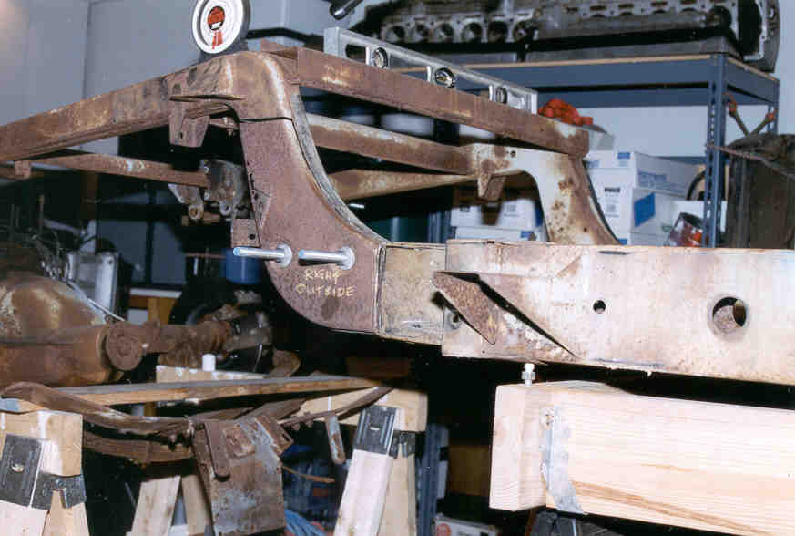
Frame after first cuts.
1/2″ All-Thread rod extends through both sides of frame as an aide to maintain the correct orientation.
Note the magnetic base protractor and spirit level.
Frame after first section removed. Original bolt hole reinforcements (and 45 years of trash) have been removed.
Note that pencil lines scribed about 1″ outside of cuts mark the eventual replacement limits.
I used a large square to make sure they are perpendicular (90°)
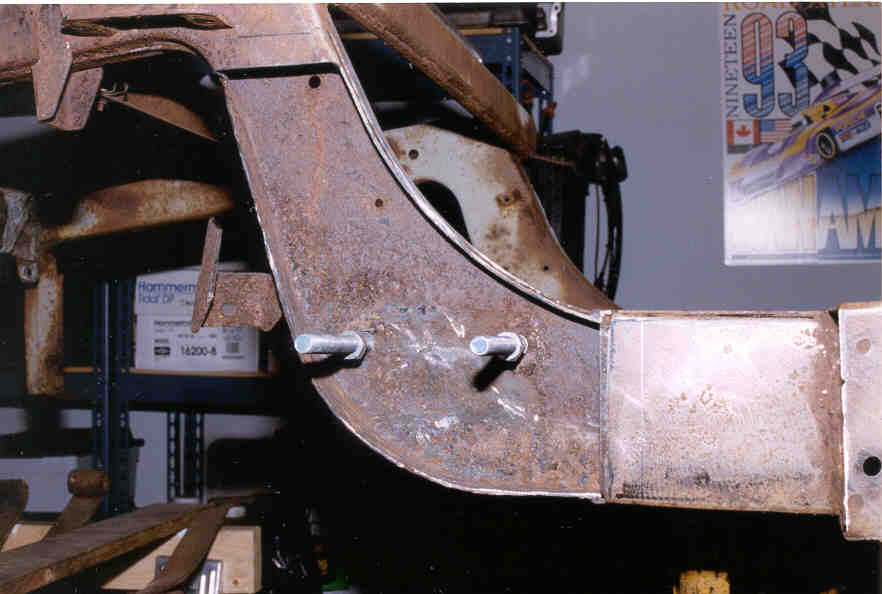
Image 3
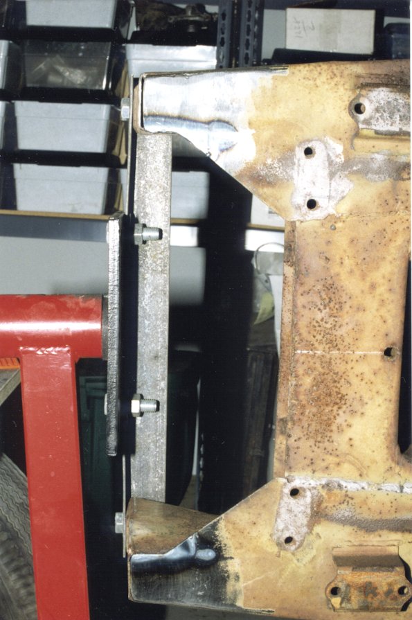
Extent of rust in “good” frame.
Before powerwashing, this frame looked solid.
I sold a (worse!) one to buy this one – Oh well…..
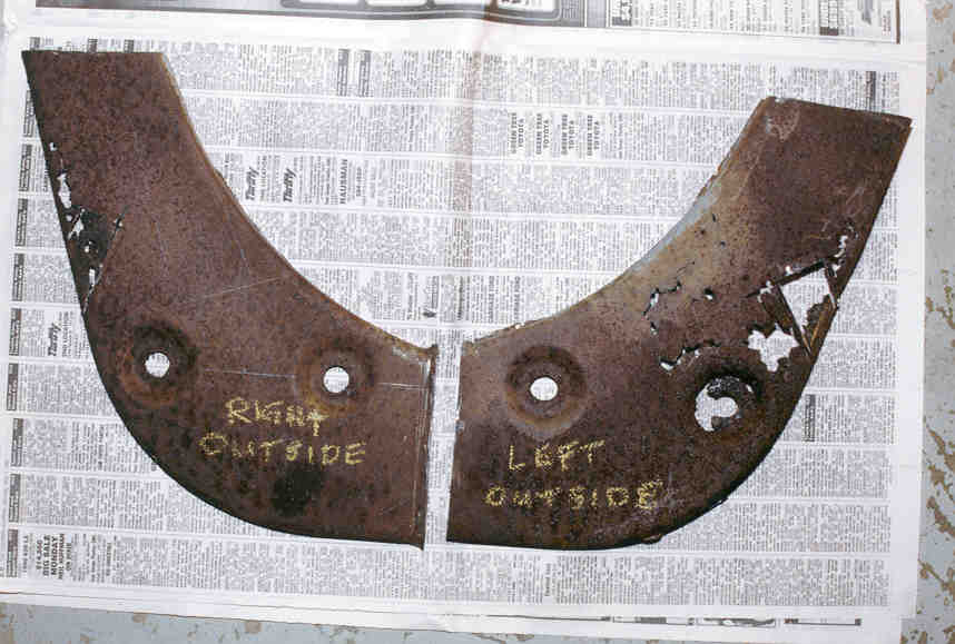
Image 41st Plate tacked in place
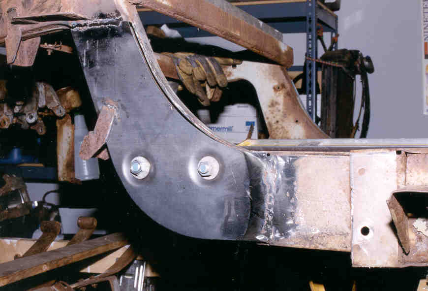
Image 5Back side of the outside plate on the right side.
One of the several stamped sheetmetal spacers that are found along the length of an XK
frame is just visible near the weld.
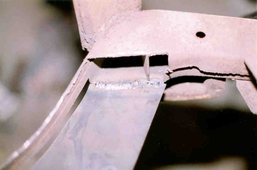
Image 6
This image shows…
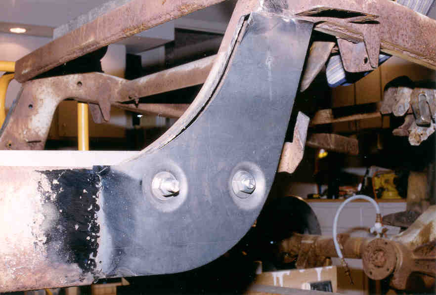
Image 7New bolt hole reinforcements. (1/2″ Schedule 40 Pipe).
Pipe is welded to the back side of the bolt-head recess on the outside frame rail.
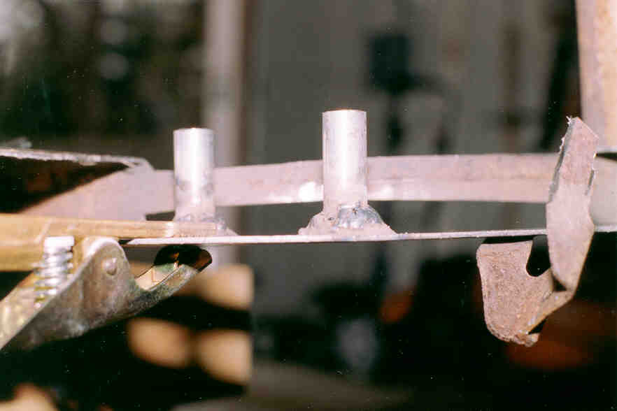
Image 8Second plate welded in.
Welded to bolt reinforcement.
Reinforcements started out longer than the width of the frame rail.
Passed through the hole in theinside face, trimmed flush, then welded.
Note “Stub” of original section slid inside of forward frame rail.
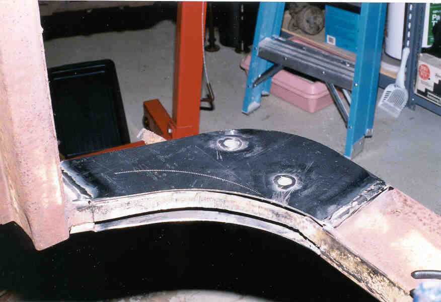
Image 9Left side, inside plate.
Bolt hole reinforcements have been welded to oversized holes in plate, cut flush, then ground smooth.
(same area as image 8, but different viewpoint).
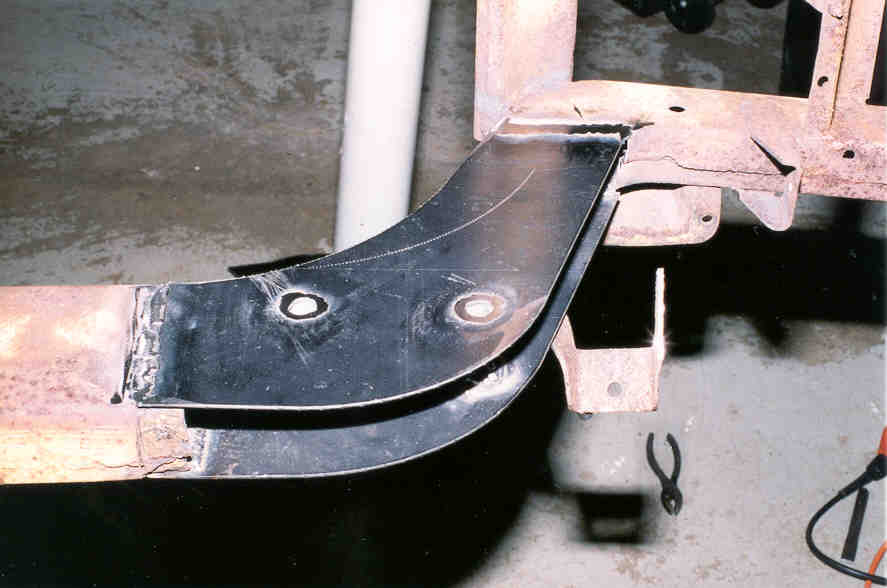
Image 10
Left side,outer plate. I replaced both the outside plates, then the inside, and finally, the front and rear strips between the two. Note the “dimples” for the damper mounting bolts.
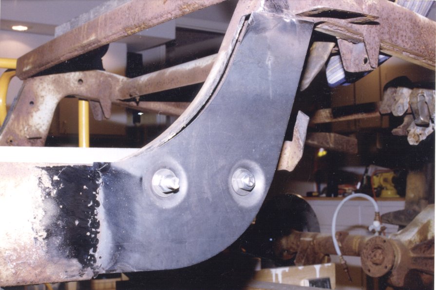
Image 11
Right side
looking at the back of the outside plate from the left.
The new outer plate was fully welded before the inner plate
(which has been removed here) was cut away.
The new plates were fabricated from 10 ga. steel.
Left side,outer plate. I replaced both the outside plates, then the inside, and finally, the front and rear strips between the two. Note the “dimples” for the damper mounting bolts.
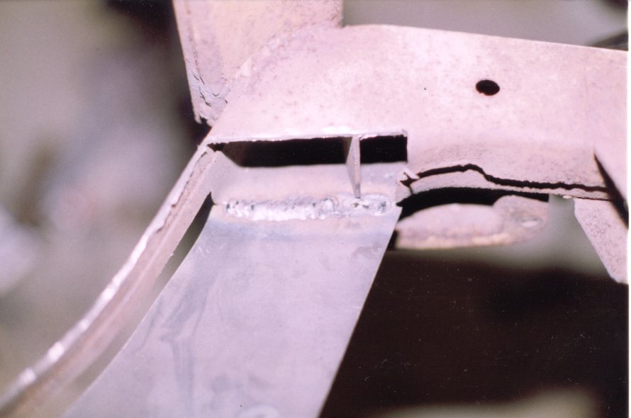
Image 12
.Right side, viewed from the inside.
Both the inside and outside plates have been welded in,
the filler strips between them remain to be replaced.
Right side, viewed from the inside. Both the inside and outside plates have been welded in, the filler strips between them remain to be replaced.
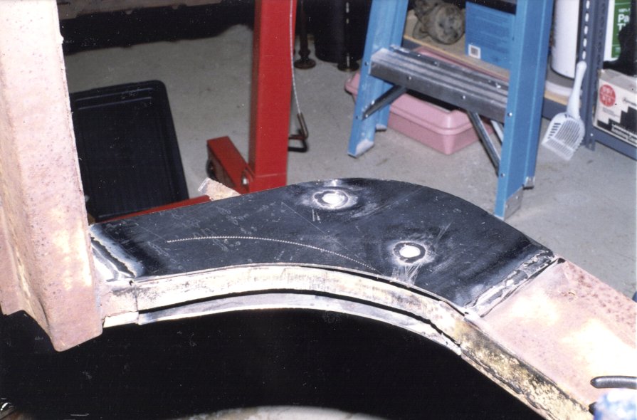
Image 13
Finished!
View with frame turned on its side.
The shiny strips along the full length of the
bottoms of both frame rails are new metal.
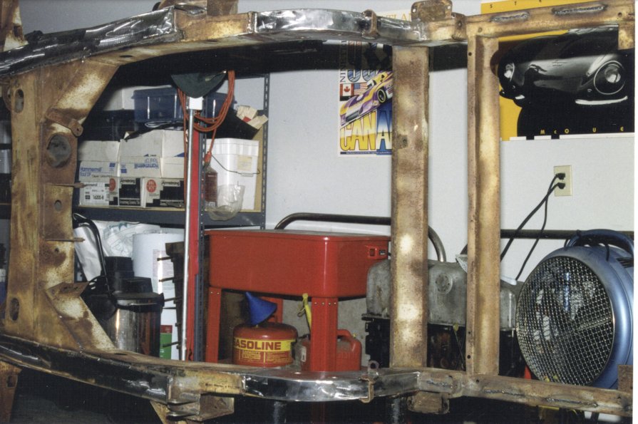
Image 14
Front of frame, bottom side.
Frame horns are new, as are the sections just
to the rear of the lower wishbone mounting holes.
The forward edge of the new rail bottoms is just visible on the right.
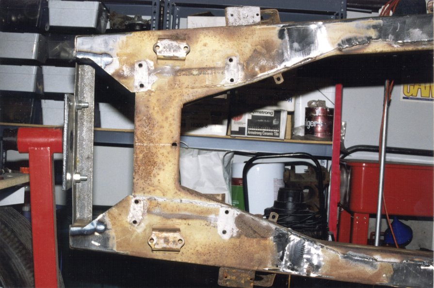
Image 15
Mounting tabs for the straps that run under the rear axle
have been reinstalled, as has the tab for the brake line mounting.
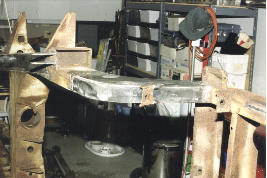
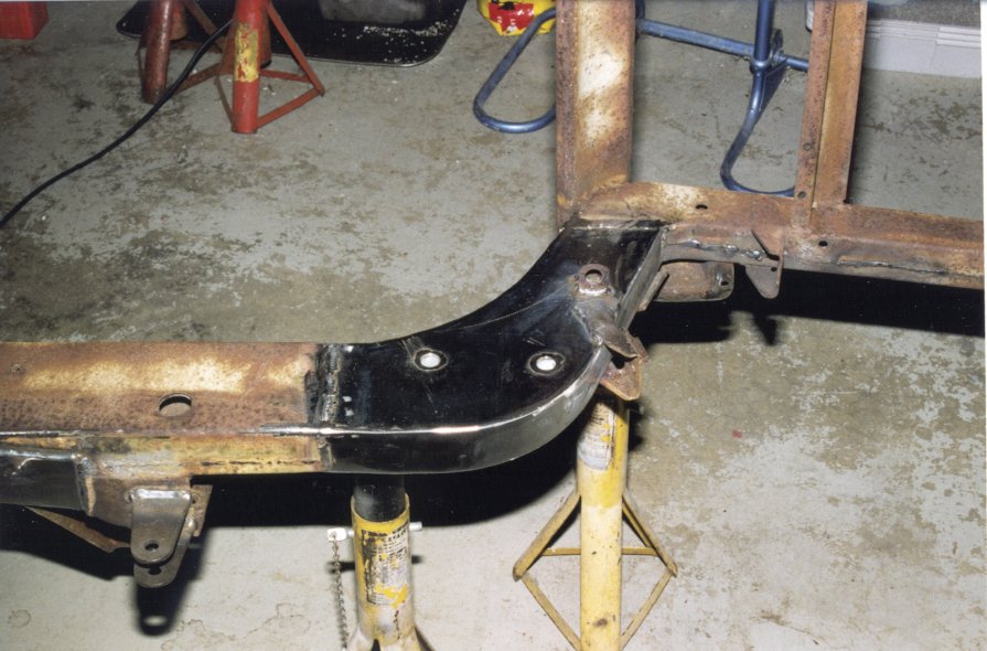
Image 16
Left side, bottom.
Almost the full length of the bottoms of both frame rails
was cut out and replaced with new strips of 3/16″ steel.
On the garage wall in the background, Patron Saint Steve McQueen
smiles down in approval from the drivers seat of his XK-SS.
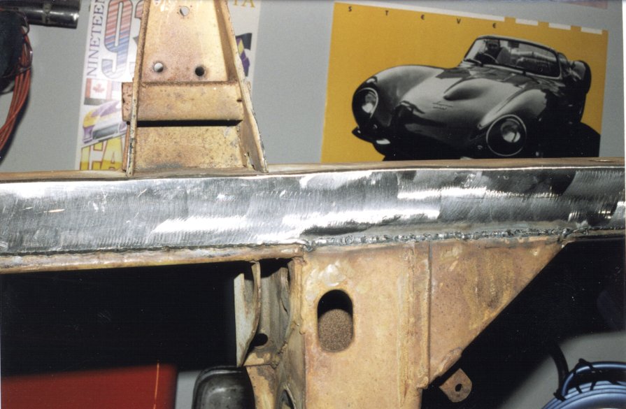
Image 17
Right side, showing completed repairs
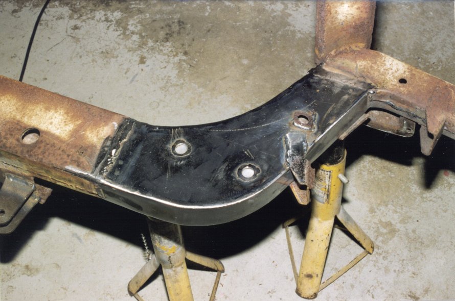
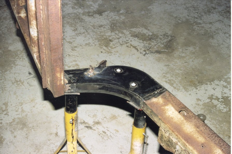
Image 18
Close-up of frame horn repair.
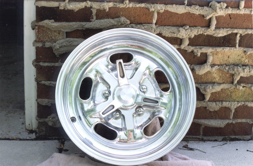
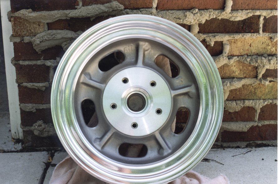
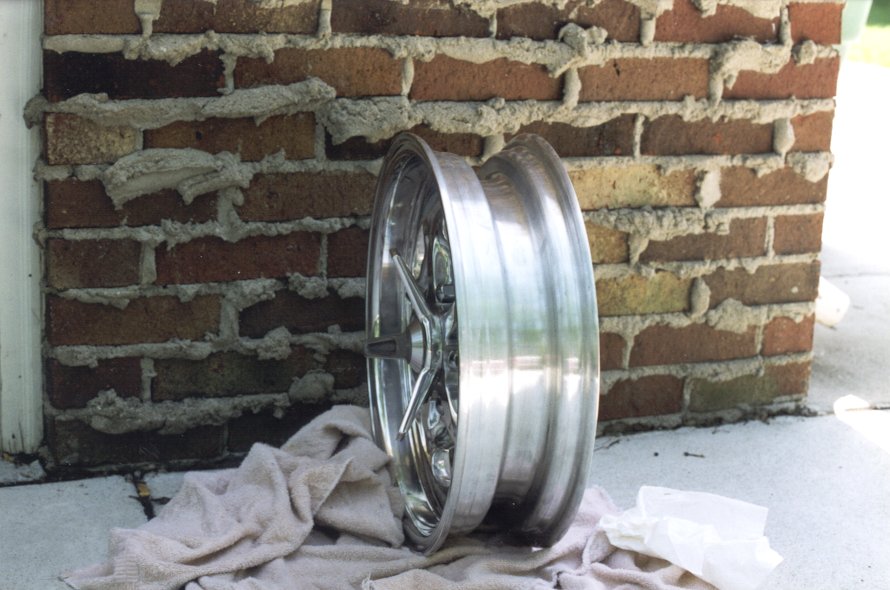
Custom” wheels in the literal sense ( $cents$?). Reproductions of the Hallibrand “Kidney Bean” wheels from the 1950’s. In fully polished aluminum alloy, 16″ x 4-1/2″, drilled for the 5 on 5″ XK hub. From Phil Schmidt at P.S. Engineering. They will accept tubeless tires and can be balanced anywhere. They are now fitted with 185VR16 Avon Turbospeed radials.