
2 – Engine ( Paul Stow, December 1, 2001 )
|
|

The AJ16 engine is based on the previous AJ6 engine found in 3.2, 3.6 and 4.0litre XJ40 models. It features a host of detailed improvements, however, to provide increased power, torque and economy.
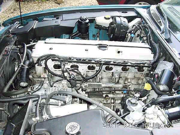
It is a straight six engine, with a pair of chain driven overhead camshafts and four valves per cylinder. XJR models feature a belt driven supercharged with associated intercooler, together with reducing the compression ratio from 10:1 to 8:1. Engine management is a significant evolution of previous systems, with diagnostics available only via the ODBII connector.
Experience so far has shown the engine to be fairly bullet-proof, though some XJR’s have needed head gasket replacement.
Reprofiled cams were fitted to later models to overcome some problems with uneven idling.
2.1 – Cam Cover and Gasket ( Paul Stow, December 1, 2001 )
An aging cam cover gasket may begin to seep oil, particularly around the cover bolt holes. The circular spark plug hole seals may also begin to weep, causing a build up of oil around one or more spark plugs. It is also necessary to remove the cam
cover when checking valve clearances and though this is not a frequent service item it is worth doing whenever the cover is removed.
To remove the cam cover, it is first necessary to remove the middle top section, by undoing the three torx bolts. Unbolt the epoxy encased ignition coils from the top of each plug and pull upward to free them from the spark plug.
Note how the wiring to each coil is of the correct length, and also note the arrangement of the wiring for the rearmost plug. Unclip the wiring and move the coils carefully out of the way. Also undo the clip and disconnect the breather hose from the right hand side of the cover.
The cam cover can be now removed by undoing the series of bolts around it’s edge and lifting gently upwards. A little effort may be needed at first to break the seal.
If you are replacing either the cover gasket or a plug hole seal, it’s worth doing all the plug seals and cover gasket at the same time. Also check the valve clearances following the procedure given below.
Seat the seals and gasket on the top cover prior to replacement. If necessary, use a little engine oil to help them stay in place. Make sure the gasket is aligned correctly, particularly around the halfmoon sections at the back of the head.
Replace the cover and gently tighten the bolts. Although precise torque and tightening procedure aren’t critical here, follow good practice by starting with the left and right side bolts in the centre and working in diagonals to the ends.
Refit the wiring to the coils and then reattach the coils to the plugs. As with a normal HT lead, they may need a good push to click into place. Now gently tighten the coil fixing bolts – they don’t need to be much more than finger tight, but there’s no need to be afraid of them either. Refit the top centre cover and you’re done.
2.10 – Oil system ( , )
2.10.1 – Oil and Filter Change ( Paul Stow, December 10, 2001 )
Warm the engine through to thin the oil and ensure any particles are not sitting in the bottom of the sump.
Raise the car to gain access and, after placing a suitable container underneath, undo the sump drain bolt at the rear of the sump. When the flow has stopped, clean the bolt, copper washer and mating surface on the sump, and refit. It needs to be snug but not overtight. Leaks are usually cured by fitting a new washer.
Use a strap wrench or similar tool to undo the oil filter. Be aware the filter will contain oil, so keep your container underneath. Clean the mating surface on the engine block and use a finger to spread a thin layer of oil over the rubber sealing ring of the new filter.
Screw on the new filter until snug, then tighten approximately a further quarter turn. Hand pressure is normally adequate for this, but if you do decide to use a strap wrench, fit it close to the base of the filter such that you do not deform or damage it in any way.
Good oil filters feature an anti drain back valve which prevents oil draining back into the sump whilst the engine is stopped and therefore provides quicker lubrication when the engine is started. The valve can normally be seen as a piece of plastic behind the holes in the base of the filter. Jaguar and Fram filters are known to have this valve.
2.10.2 – Oil Cooler Bypass ( Paul Stow, December 10, 2002 )
Some markets require a separate oil cooler to be fitted, the feed for which comes from the block beneath the oil filter. Where an oil cooler is not required, a bypass is fitted, consisting of a small 180 degree steel hoop-shaped pipe, again fitted next to the oil filter.
The connection is sealed by small rubber O-rings which do fail over time and produce an oil leak.
Replacement requires only unbolting and removal of the bypass pipe to gain access.
2.10.3 – Oil Pressure Sender ( Paul Stow, December 10, 2001 )
The sender is located on the side of the engine block, underneath the inlet manifold toward the rear, and can be identified by the large diameter fixing nut. Removal is simple once you have access. On replacement, Jaguar recommend that a thread sealer such as Loctite 562 be applied to the exposed threads once the sensor has been screwed in by a thread.
Early X300’s had a true pressure sensor, which is prone to erratic readings as a result of the carbon track of the potentiometer wearing out. Because of this, and customer concern over reduced oil pressure at idle, which is perfectly normal, later X300’s and dealer repaired early models had a simple pressure switch fitted instead. This is linked with software reprogramming the instrument pack to cause the needle to sit either at the mid-point, or at zero dependent on the switch.
2.12 – Idle Speed ( Paul Stow, December 1, 2001 )
The normal hot idle speed is 750 – 800 rpm in Park or Neutral and 650 – 750 rpm in Drive. The speed is determined by the ECU, which drives the Idle Speed Control Valve located in the throttle body, and it is not adjustable. Note the ISCV is a different device from that used on the previous AJ6 engine.
If the idle speed is incorrect and no other problems are apparent, check for a clogged or dirty throttle body, correct operation of the throttle position sensor or a weak throttle return spring.
2.2 – Valve Clearances ( Paul Stow, December 1, 2001 )
Remove the cam cover as described a bove.
Each valve must be checking using a feeler gauge inserted between the back of the cam lobe and actuating bucket, when the lobe itself is pointing vertically upward. The engine can be turned in a clockwise direction using a socket on the crankshaft pulley bolt, and this can be made easier by removing the spark plugs first.
Adjustment is beyond the scope of many home technicians, as it requires removal of the camshafts and the insertion or removal of shims under the the actuators. The basic process is similar to that used on the XJ40 and described in the Haynes manual. Minor differences from specification are not a major cause for concern, but an undersize gap on an exhaust valve is likely to cause that valve to overheat and burn out.
Replace the cam cover as described above, checking the condition of the gasket and plug hole seals.
2.3 – Timing Chains ( Paul Stow, December 1, 2001 )
The chains are of the duplex variety and are extremely reliable in service. An oil based tensioner is used, which also appears reliable. Rattling from the front of the engine, particularly when cold, may however be due to ageing or failing of the tensioner or plastic chain guides.
Note, however, that because the tensioner is driven by engine oil pressure, there may be a small noise for a couple of seconds at start-up if the engine has been left for some time and this is not a cause for concern.
2.4 – Inlet Manifold Removal ( Paul Stow, December 1, 2001 )
|
|
The procedure for this on normally aspirated models is slightly different to that for the XJR, as detailed below. However, the overall sequencing of tasks is essentially the same.
The manifold is a single casting with, in the case of the XJR, an intercooler welded onto the inlet side. The intercooler inlet is fed by the supercharger, which in turn is fed from the throttle body mounted underneath the inlet manifold. Incoming air is routed from the air filter over the top and down the rear side of the intercooler to reach the throttle.
Removal and refitting of the manifold is somewhat fiddly, but not complex. Make sure to note the position of pipes and electrical connections as they are removed, but Jaguar has helped here by ensuring most pipes and electrical connectors are shaped in such a way that they can only go back one way.
Begin by removing the trim cover from above the fuel injectors, which is held in place by three torx head bolts. Working along the line of injectors, squeeze the metal clip on the electrical connector to each injector and pull upward to release it. You will need to gently pull up on the plastic mounting which holds all the connectors in order to stop them clicking back in again. To avoid bending the mounting bar too much, you will probably need to release the next connector before the previous one can be fully freed.
Eventually all the connectors are released and can be moved away – it is possible to route the wiring over the front corner of the engine and so gain a bit more working space, but it is not necessary to trace and disconnect the injector wiring.
Slowly unbolt the fuel inlet and return pipes at the front of the injector rail / pressure valve assembly, allowing any remaining fuel pressure to dissipate and using a rag to mop up any spillage.
Disconnect the air intake hose. Again to make more space, disconnect the MAF connector ( halfway between air filter and manifold ) and remove the whole air intake trunking from the air filter end. Also disconnect the cam cover breather tube, which is routed between branches 5 and 6 of the manifold.
On the XJR, disconnect and remove the intercooler air inlet hose and unbolt the associated elbow. The plastic line going into this is for braking vacuum and is reluctant to come out of the elbow, so is best left in place. The elbow can be parked out of the way above the heater pump and hoses. The intercooler coolant hoses are at a fairly high point of the system, but it’s less messy to drain at least some coolant out of the system before removing them. Also at this stage, unbolt the intercooler supporting bracket and associated dipstick tube bracket.
From under the car, disconnect the air duct feeding the throttle body from the rear side of the manifold assembly. Note that it is not easy to remove the rear ducting section from the manifold. Disconnect the breather pipe attached to the rear side ducting.
The manifold is attached to the head by nuts above and bolts between the inlet ports. Undo the nuts, which is easy, and undo the bolts, which is fiddly. You will need slim fingers or a pair of long nose pliers to remove the bolts when they are loose. Remove the connector support bracket from the rearmost mounting stud.
You may need to rock the manifold a little to free it, but it should now be possible to move it backward such that it is resting on the ends of the mounting studs. This gives you the extra clearance and movement needed to disconnect the wires routed down between ports 2 and 3 of the manifold.
On the XJR, these connectors link to the oil pressure sensor on the block, anti-knock sensor ( I think! ) on the block, throttle position sensor on the throttle body, Idle Speed Control Valve also on the throttle body, and Intake Air Temperature sensor on the underside of the intercooler.
Thread the electrical connectors between the manifold ports and out of the way. It is now possible to gently lift the manifold away, checking carefully for any forgotten attached pipes or cables. Beware of remaining coolant in the intercooler on XJR models.
Check the condition of the gasket. It can be reused if there are no potential leaks, but it’s not expensive to replace. Ensure head and manifold surfaces are clean before refitting.
Refitting is the reversal of removal. The anti-knock sensor is tricky to get on, but will eventually give in. There are two similar style connectors, but one has a long lead and one a short lead, so you can’t really mix them up.
Loosely attached the manifold using front and rear mounting studs, not forgetting the connector mounting bracket at the rear, whilst attaching the breather hoses, mounting strut, dipstick bracket and air ducting. Use long-nose pliers to get the bolts in between the inlet ports and get them all started before progressively beginning to tighten.
On XJR’s, attached the coolant hoses and refill the system. For all models, replace the MAF and associated ducting, fuel send and return lines, the fuel injector connectors and their cover.
Check again carefully that all pipes and connectors have been replaced before starting the engine.
2.5 – Exhaust Manifold ( Paul Stow, December 1, 2001 )
|
|
Undo the six bolts securing the heatshield and remove it. On US models, remove the EGR.
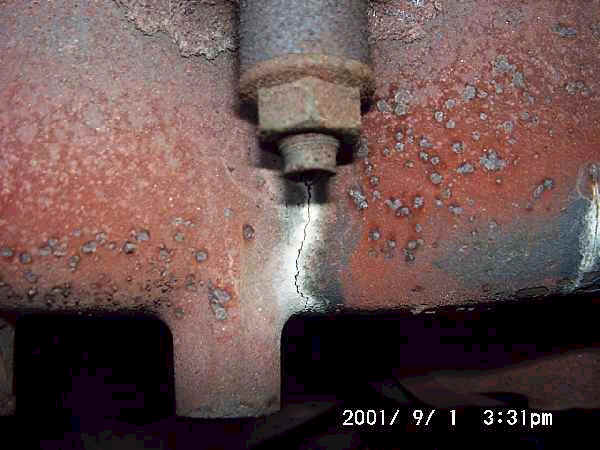
Inspect the manifold for cracks. These are usually obvious, and may also have caused a dark line of soot on the manifold and heat shield underside. They cause increased noise and can affect ECU inputs from the Oxy sensor in the downpipe. Use a dentists mirror or similar to check the underside of the manifold.
A reasonable cure may often be made with a wet solution of exhaust putty pushed into the cracks, or a heat resistant epoxy, but a long term fix requires welding or replacement. Specialist welding is required, as a simple furnace weld is likely to warp the manifold and cause more problems.
Undo the exhaust downpipe to manifold bolts and lower the exhaust. This will be much easier if the bolts have been soaked in penetrating oil for a few hours beforehand.
Undo the manifold nuts and gently rock the manifold to release it.
Clean the manifold and head surfaces thoroughly before replacing the manifold, and use a new gasket. Otherwise, refitting is the reversal of removal.
If removing the lambda sensors from the downpipes, take care to mark them and reinstall each in it’s original location. If they are reversed, the ECU cannot understandwhat is happening in the engine and will set a check engine error code.
2.6 – Supercharger Idler Pulleys ( Paul Stow, December 1, 2001 )
The supercharger drive belt on XJR models runs over a fixed idler pulley, mounted in front of the thermostat block, and an adjustable idler pulley mounted directly on the front of the engine.
The adjustment is done by a movable pulley, sliding up and down on a threaded bolt. The top of this bolt can be seen from the right hand side of the car, point upward at a 45 degree angle just in front of the engine block. The head itself is just a squared off shaft, but can be turned with a decent pair of pliers.
These pulleys have been known to seize, thus throwing the drive belt. However, in itself this doesn’t seem to cause any damage and, apart from significantly reduced power, the engine will continue to run without even illuminating the Check Engine light.
To remove the supercharger belt, first release tension on the belt with the adjuster.
Loosen the four fixing bolts which locate and hold the adjuster. The adjustment itself can now by turned, anti-clockwise to move the pulley down and release the tension. A good few turns are required, and a gentle tap on top of the pulley may help it to move initially. Once loose, the belt can be removed.
The idler pulley’s can be removed simply by undoing the central fixing bolt. However, on the adjustment pulley it may be better to remove the mechanism as a whole by undoing for four fixing bolts. This will allow the pulley to be removed without straining against the adjustment bolt itself.
Refitting is the reversal of removal. The pulley bolts need to be tight, but not excessively so. Make sure
2.7 – Supercharger ( Paul Stow, December 1, 2001 )
The supercharger itself is of the Eaton type, which differs from the Rootes model in having helical shaped vanes. The unit is reliable and the only required maintenance is to check the oil level, which can be read on the stick attached to the cap located at the front of the supercharger. Note the use of a special long life synthetic oil, available from dealers, and there is no recommended change.
Topping up is done by removing an allen type bolt located to the front left of the supercharger body.
The bypass circuit is actuated at idle or low throttle settings and consists of a pipe and vacuum actuated control valve located at the back of the supercharger allow air to pass directly from the inlet side to the outlet.
2.8 – Auxiliary Belt Tensioning ( Paul Stow, December 1, 2001 )
This is done in the traditional way by adjusting the position of the alternator. It is safest, though not necessary, to disconnect the battery prior to undertaking this task, avoiding the risk of a spanner finding an uncovered live terminal on the alternator.
Loosen the long pivot bolt on which the alternator moves. Loosen the outer bolt on the threaded tensioning arm and give yourself enough adjustment to play with.
Using a bar or strong piece of wood, push the alternator outward, thus further tensioning the belt. This allows adjustment using the inner bolt on the tensioning arm.
If it is required to release tension, perhaps to remove the belt, then wind the inner bolt down the tensioning arm whilst continuing to push the alternator outward. Release the alternator and push inward to allow the belt to be removed.
When refitting, lever the alternator to obtain the correct belt tension and then wind up the inner bolt on the tensioning arm to hold the tension. Wind down and tighten the outer bolt on the tensioning arm, and finally retighten the pivot bolt.