written by Scot Thompson
with technical expertise by Dick Maury
20 October 2022
I’ve had a very frustrating experience with my Hubs on the rear of my 1963 Series 1 E-type FHC. A broken Splined Shaft yoke, a damaged Inner Seal cup, worn and pitted bearings, abused threads on the Outer Fulcrum Shaft and my own lack of confidence thinking I incorrectly pressed the Hub into the Hub Carrier when, in fact, I did it right. Not to mention the wrong parts shipped to me. And I still had to replace the new bearing and seal I wrecked! It has been a learning experience to say the least. I wanted an easier, surer path forward and so I turned to Jaguar guru, Dick Maury, recently retired from Coventry West and working in his own shop just east of Atlanta.
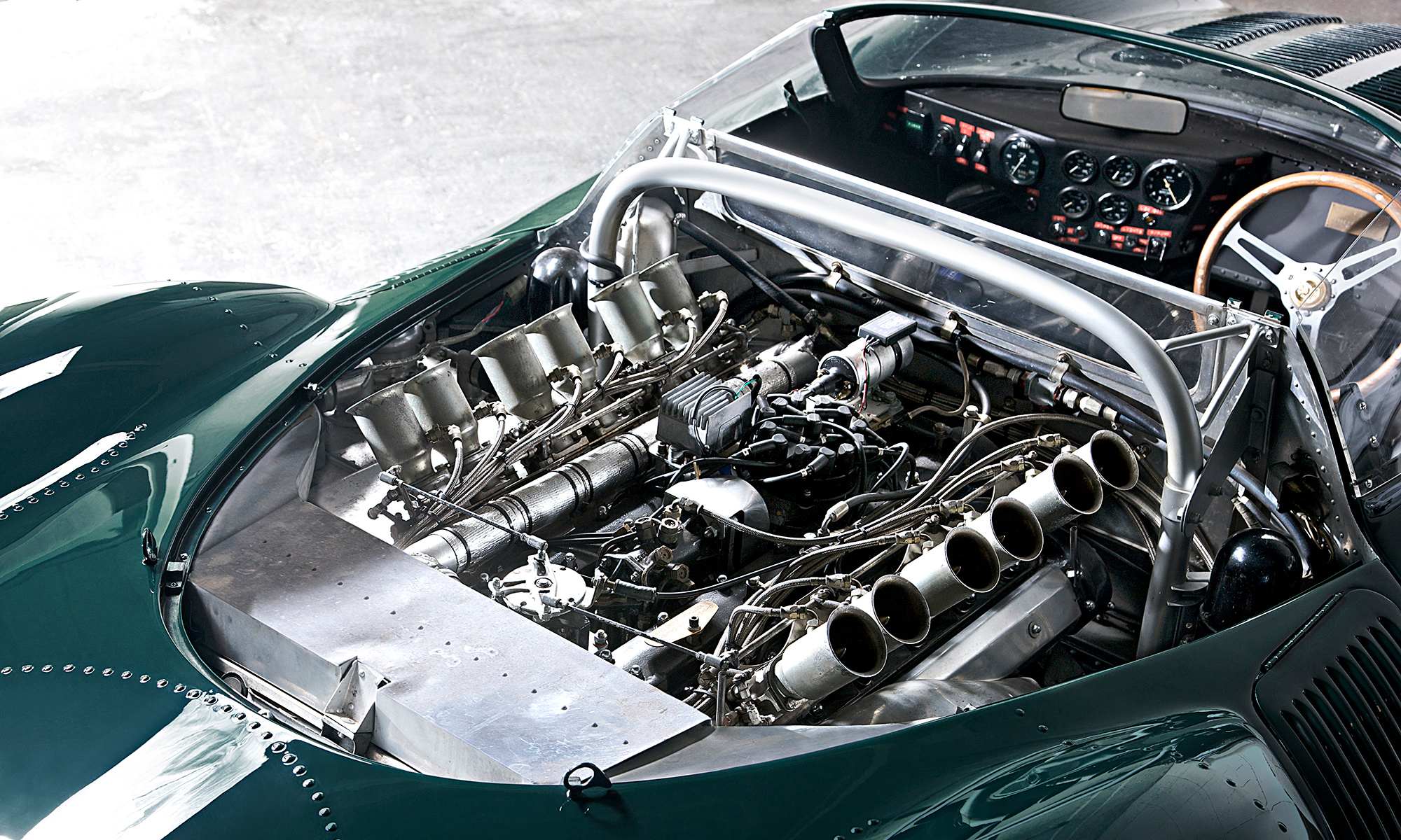
The Car
The build date on my car is 26Sep62. It has the 3.8 liter engine. That is important information as my car’s date is critical to determining what type of Outer Seal is required in the Rear Hub. This car has more in common with a ’62 E than it does with most ‘63s. My car needed the small seal as provided with “early” XKEs. Early being relative of course. At some point in time Jaguar went to a larger seal. Records indicate the change occurred at E-type 4.2 OTS from 1E.1237/1E10979 (RHD/LHD); 4.2 FHC from 1E20639/1E.31003 (RHD/LHD); and all Series 1 2+2 and all Series II & Series III have the larger Outer Seal. Possibly, there are some 3.8 cars that did receive the larger Seal as well. I don’t know the full reason for the swap but it greatly – in a positive way – affects how the Outer Bearing is installed. I do almost all my own work, but I goofed once on this Hub and I wasn’t anxious to repeat the effort. Besides, Dick offered to also show me how he determines the correct Pre-load Spacer size. Well, that was an offer too good to turn down. What he does is pretty amazing – quick and precise — and pretty obvious in retrospect. Read on.
The Maury Method
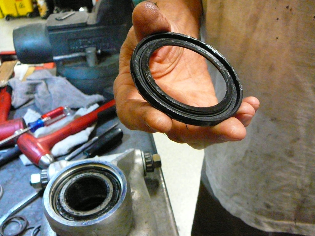
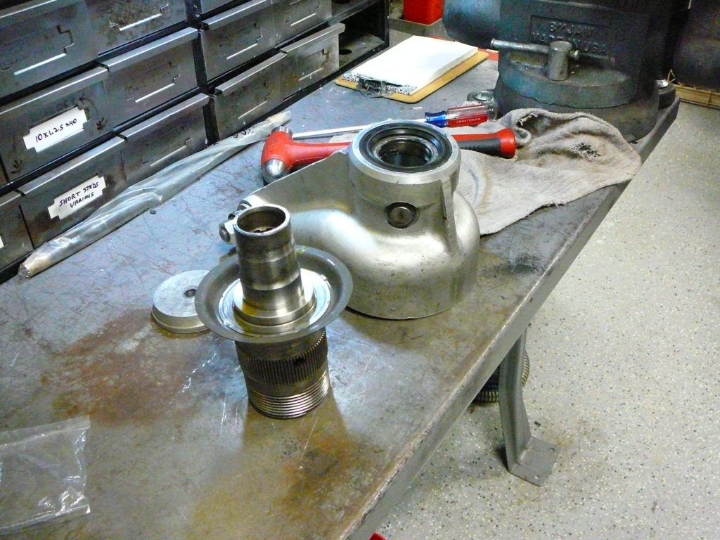
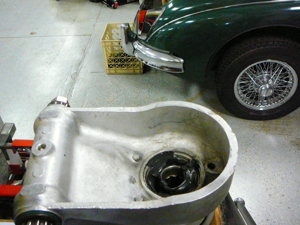
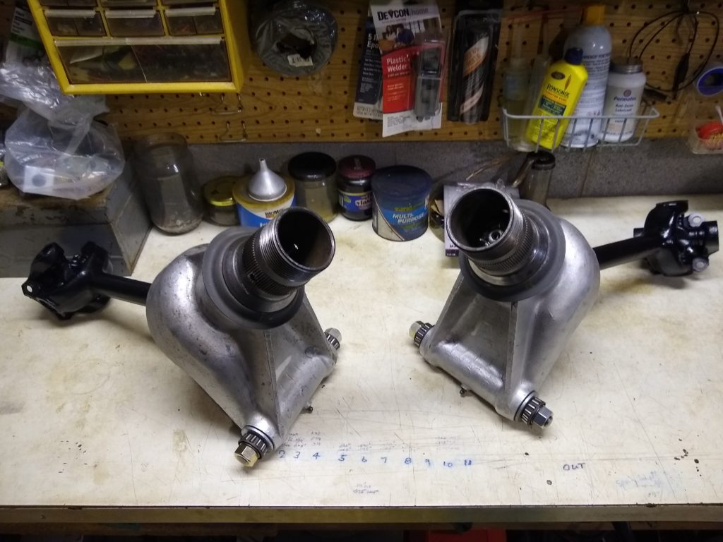
First press the Inner Bearing Outer Race and the Outer Bearing Outer Race into the Hub Carrier. (For clarity and triteness going forward I’ll refer to the parts of the bearings as a Cup and Cone – that is the Outer Race and the Inner Race in English speak.) With a small-seal Hub, with the bearing Cups in place, the Outer Seal Seating Ring must then be pressed onto the Hub. (The Seal Seating Ring is also referred to as the Seal Track.) Next, place the fully greased Outer Bearing Cone on its cup and press the Outer Seal into place on the Hub Carrier. Check to ascertain the tension spring on the Seal is in place. Also monitor that this spring remains in position as the Seal is pressed into the Hub Carrier. It is not unusual for the spring to pop out. Some grease packed around this spring may help avoid that. The Seal will then hold the Outer Bearing in place. The 2nd picture shows the Hub and Hub Carrier ready to be brought together. Do not forget to put the Seal into place before pressing the Hub into the Outer Bearing; there is no other opportunity to install it and you’ll be redoing things if it’s forgotten. This part of the process is much different than for a Hub with a large outer seal. With those cars, the Outer Seal is sufficiently large to fit over the Outer Bearing. Hence the Outer Bearing can be pressed onto the Hub and made tight to the Outer Seal Seating Ring, the Outer Seal then can be pressed into the Hub Carrier and the Hub with its installed bearing slipped through the Seal and into the Hub Carrier.
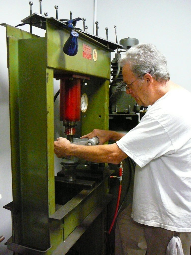
With the small seal Hubs, the next step is to marry the Hub to the Hub Carrier by pressing the Hub into the Outer Bearing. You may find it easier to press the Hub Carrier with its inside up onto the Hub that is sitting on the press’s table or bolster thereby avoiding finding secure mounting supports that fit the odd shape of the Hub Carrier. I recognize the shop manual states, “…so that the Outer Bearing will be at the top.” That is unfortunate as it is much easier with the Outer Bearing facing down. Here’s Dick Maury driving the Hub Carrier onto the Hub. You’ll know when the Outer Bearing meets up against the Seating Ring when the pressure on the floor jack goes up. On Hubs with Water Throwers, the interface between the Bearing face and the Seating Ring is not visible when the two come together so this is a “feel” operation and it helps to have a pressure gauge on the floor press.
[A word of caution for those who, like me, are doing this the first time. I got to this point quite successfully but did not know what to expect once the Hub was fully seated into the Outer Bearing. This picture is my setup on my floor press. Note that Dick presses the two components together Hub down. I expected the Hub to remain somewhat firm in relation to the Hub Carrier but it does not. It flops around a bit – well quite a bit. I thought I broke something like the Hub Carrier itself by applying too much pressure with the floor press. I had been closely monitoring the progress of the Hub going into the Bearing by watching the shiny side of the Seating Ring assuming I would observe the shiny edge shrink as the Seal slipped over it. With the Water Throwers in place, this is not feasible and when my press became firm and motion stopped, I pulled the assembly off the floor press to check it. I panicked when I felt all the movement and thought something was terribly awry. It wasn’t. At this point in assembly the Bearing is on the Hub, the Seal is in place and the Hub can freely move within the bearing Cup – only the seal is keeping the Hub together with the Hub Carrier. The movement between Hub and Hub Carrier feels … well rather loosey goosey. That is normal; I thought something broke. Learn from my foolish and expensive error!]
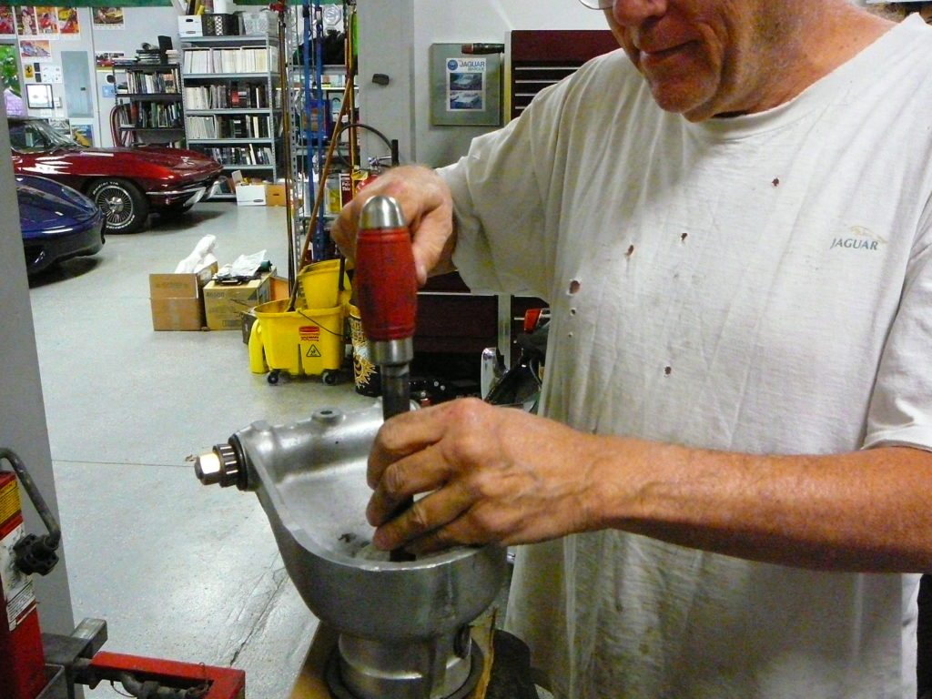
With Dick at the controls we carried right on to the next step. The whole process, including determining the Spacer thickness and fitting the axle into the Hub takes less than one hour. We went slow for my benefit and to explain things along the way. More on that later. The next step is to fit the greased Inner Bearing into the Hub Carrier and fill the Hub Carrier cavity with grease. This is where the Maury Method gets interesting and it requires a bit of feel very similar to how we all have installed wheel bearings on trailers, normal car fronts and just about any axle that uses tapered bearings. The pre-greased Inner Bearing is pressed onto the Hub using a dead blow hammer and a bearing/seal driver. It is important to have the bearing pre-greased because it is not coming out again! But it needs to be adjusted properly. First Dick secures the Hub/Hub Carrier assembly in a vice after first protecting the knock-off threads. He then sets the bearing on the inner end of the Hub and drives it into its Cup to a point where the Bearing just comes into contact with the Cup. Nothing fancy going on here. Just pound the Bearing onto the Hub. What he is now going to do, because the Bearing and Cup have a lot of grease on them, is to tap the Bearing down to a point where one can feel the Outer and Inner Bearings become too tight. This is felt by rotating the Hub Carrier and it will feel just like a trailer wheel bearing has been overtightened. For my benefit, he drove the Inner Bearing down to a point where the only turning resistance of the Hub Carrier was due primarily to the Outer Seal and grease. That is a no pre-load point – again just like a wheel bearing on a trailer axle screwed in just finger tight. So I now know what a loose bearing set feels like. Then he drove the Inner Bearing in a bit further until a point where it felt too tight. Dick believes it is important to slightly overtighten the Bearing to squish the grease out and minimize the effect of the grease on the bearing rollers and the cup. Don’t overlook this step. Next he takes a large rubber hammer and taps the Hub Carrier upwards thereby separating the Outer and Inner Bearings a little bit. He does this hammering several times until one can feel the Hub Carrier rock a little when wiggled. This is akin to setting a trailer’s wheel in place on its axle and wiggling the wheel to feel if the nut holding the bearing is too loose or too tight. The Hub Carrier offers plenty of leverage to make this judgement. He’ll then gently tap the Inner Bearing down, checks for wobble, and taps it down again to a point where absolutely no wobble can be produced by rocking the Hub Carrier. He then verifies the Hub Bearings do not feel too tight. At this point the Bearing Pre-load is set. I found this to be an easy process and no more difficult than the many wheel bearings I have installed in my lifetime. Not too tight, not too loose.
With that completed the Hub Carrier cavity is packed with wheel bearing grease. Within the Jaguar-owners community there are differing opinions on whether the Hub Carrier should be packed full as the factory states or not. Some say just to pack the bearings and others pack the bearings and then fill the cavity. Dick Maury has been rebuilding Jaguars for over 40 years and has done hundreds of cars. In all that time he has never had a wheel bearing fail using his method so I’m electing to adopt his method and pack the Hub Carrier cavity. I can see absolutely no harm in doing so.
On to the part I most dreaded – determining the Spacer thickness required to maintain the Pre-load. Note what was just stated, “maintain the Pre-load.” With the Maury Method, the Pre-load is now set, so you simply need to find the Spacer that will maintain it. The Jaguar “E” Type Series 1 and 2 Service Manual gives a method to determine the pre-load of the wheel bearings by fitting a Special Collar (Tool No. J.15 – essentially an oversized spacer held in contact with the Inner Bearing face by a collar). Then the Manual does confuse things by stating to place the Special Collar on the hub prior to placing the inner bearing inner race (the Cone) on the hub. That, of course, won’t work as the Inner Bearing has to be set onto the Hub first. The point is the Manual presents a method to consistently measure the end-float between the Hub and the Hub Carrier (this is also the looseness, the gap, the end-float between the Outer and Inner Bearings) by use of a Special Collar that will create an end-float larger than ultimately will be required. Then the desired specified End-Float (between 0.002” and 0.006”) can be calculated by subtracting the desired value from that measured when using the Special Collar and then subtracting that resultant from the Special Tool’s equivalent spacer thickness of 0.150”. This calculation will determine the Spacer thickness needed to achieve the specified value. Oh dear! That was a mouthful!
Before we get on with the Maury Method, let’s pause for a bit and talk about pre-load and end-float, what Jaguar means, and how the automotive industry has become wiser about properly setting up opposing tapered bearings since the days the XKE was created. First pre-load and end-float. Bear with me if this is very basic for those readers who understand this stuff. I’m writing here to help those who do not. Pre-load is the loading of a bearing that creates some resistance to turning. The pre-load squeezes the bearing and hence its rollers so they don’t rattle around in their cage. In the case of opposing tapered roller bearings like we have in the E-type, pre-load squeezes the bearings towards each other. The resistance thereby created can be measured in the torque required to turn the component(s) supported by the tapered bearings. We are not talking about the force to get the parts turning – that is called stiction – but the turning force, the torque, to keep the parts rotating. We are talking about lb.-inches of torque…not very much normally. Sometimes it is difficult or inconvenient to measure the torque directly so another parameter can be employed and that is end-float. But wait you say! End-float is how much one part moves back and forth relative to another. Hold that thought. If you can measure how much a part moves back and forth, you can find the point where the part doesn’t move at all. You can then calculate how to put a bit of squeeze on that part or parts. Sort of like negative end-float. E.g., assume two hollow tubes are slipped on a rod and nuts screwed on to that rod to the end of the threads at each end. And assume the tubes then cannot be slid back and forth because they are just touching each other as well as just touching the nuts. That condition is zero end-float. If you filed off 0.010’ of one tube they would move relative to the rod and each other by 0.010” end-float. However, if you didn’t file anything off the tubes but instead add a 0.010” thick washer between the tubes and then screw that assembly together until the nuts stop, you will have created a pre-load or a squeezing force on the two tubes. Maybe think of that as negative end-float. And that is exactly what Jaguar did with the Outer Fulcrum Shaft assembly: they used washer-like shims to create a squeeze of, on average, 0.001” pre-load (or negative end-float). I hope the readers understand this: pre-load can be specified either in inches of “squeeze” or in turning force resistance like lb.-in.
It’s been a long path to get to this next point, but if you don’t understand pre-load and end-float, then you will be lost going forward. While Jaguar did use negative end-float or pre-load when setting up the Fulcrum Shafts, they choose to used actual end-float to set up the tapered wheel bearings that are used in the XKE. Unfortunately. It is unfortunate because since the days when the XKE was introduced the automotive industry realized that tapered roller bearings function better and last longer when they are set up with some actual pre-load. Jaguar also came to this same conclusion and on later cars, using the same vaunted Jaguar IRS configuration as the E-type, they issued Hub Bearing set up specifications no longer based on actual end-float but rather with a pre-load. Therefore, the E-type Service Manual specification of using an end-float of 0.002” to 0.006”, nominally a 0.004” average, is inappropriate for setting up the bearings in our cars today. 0.004” of actual end-float will cause wheel wobble.
The Maury Method of setting up the wheel bearings will result in zero pre-load or a slight pre-load depending on your “feel” for assessing the resistance to turning of the Hub Carrier and adjusting the Inner Bearing. Dick believes finding the zero-pre-load point as he does will result in a slightly increased pre-load when the Splined Shaft is tightened fully. This is good and is due to squeezing more grease out of the contacting points and the overall compressing of all the parts together. Once the Inner Bearing is set and the Hub Carrier cavity filled with grease and before the Inner Seal if fitted, finding the Spacer necessary to maintain the pre-load can begin. This was so easy it was actually fun. But it may be a little obtuse to understand why it works. I’ll describe it first and then explain and show why it works like Dick says.
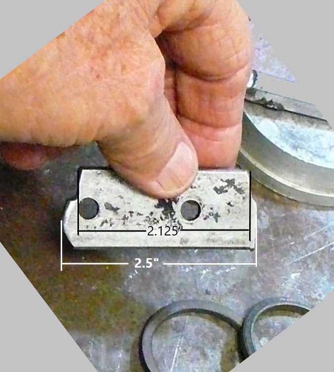
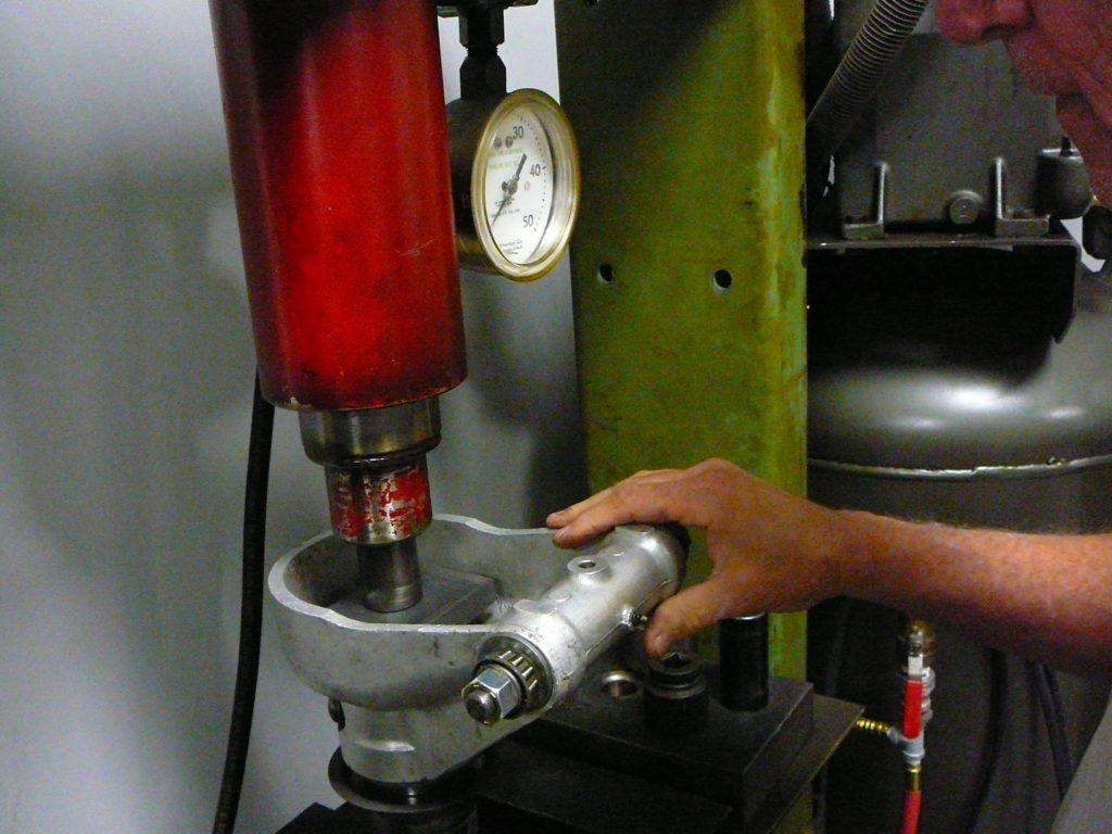
To determine the Spacer thickness a few items are required: a special Maury Gauge is used, a supply of Spacers is helpful, and a decent dial caliper. But understand that we’re not so interested in the Spacer’s absolute thickness but rather its relative thickness. We just want something that will keep the Bearing set up that we just completed. Above is a picture of Dick’s special gauge, I’m calling it the Maury Gauge, and his supply of Spacers. You should be able to zoom into see the gauge, but if not here is a closeup.
Quite sophisticated isn’t it? Uh huh. I think Dick told me it was some left-over part off an air conditioning bracket! At lease it came from a Jaguar. There are a couple of key points to the simple Maury Gauge however. The two long edges are flat. Parts of it are rounded for ease of handling. See the notches on the top side? Those are so the gauge can be used with the Inner Seal in situ. The long side on top is 2.125” and the other is 2.5”. They could be the same at 2.125” but the extra length at 2.5” makes it a bit easier to “feel” the Bearing Face. You might now wonder If the gauge can be used with the Hub on the car? If you are, the answer is, “indeed!” [This technique of on-the-car bearing adjustment is described at the end of this article.] Now that we have the Inner Bearing in place and we’ve a pile of Spacers to choose from and a special tool to use, let’s see what we are trying to do.
Here is a picture I borrowed from David Langley. I’ll leave this fairly large so it can be read easily. The inner most circle is the end of the Hub and that is where the Spacer will sit. Moving outward, the next silver/gray circle is the Inner Bearing Face. What one is attempting to do using the Maury Method is find a Spacer that will sit on top of the end of the Hub and that Spacer’s top surface will align exactly with Face of the Inner Bearing. Because the Bearings are already properly pre-loaded, you don’t care what the Spacer thickness is but only that it is perfectly flush with the Bearing Face. The Maury Gauge makes it easy to do that.
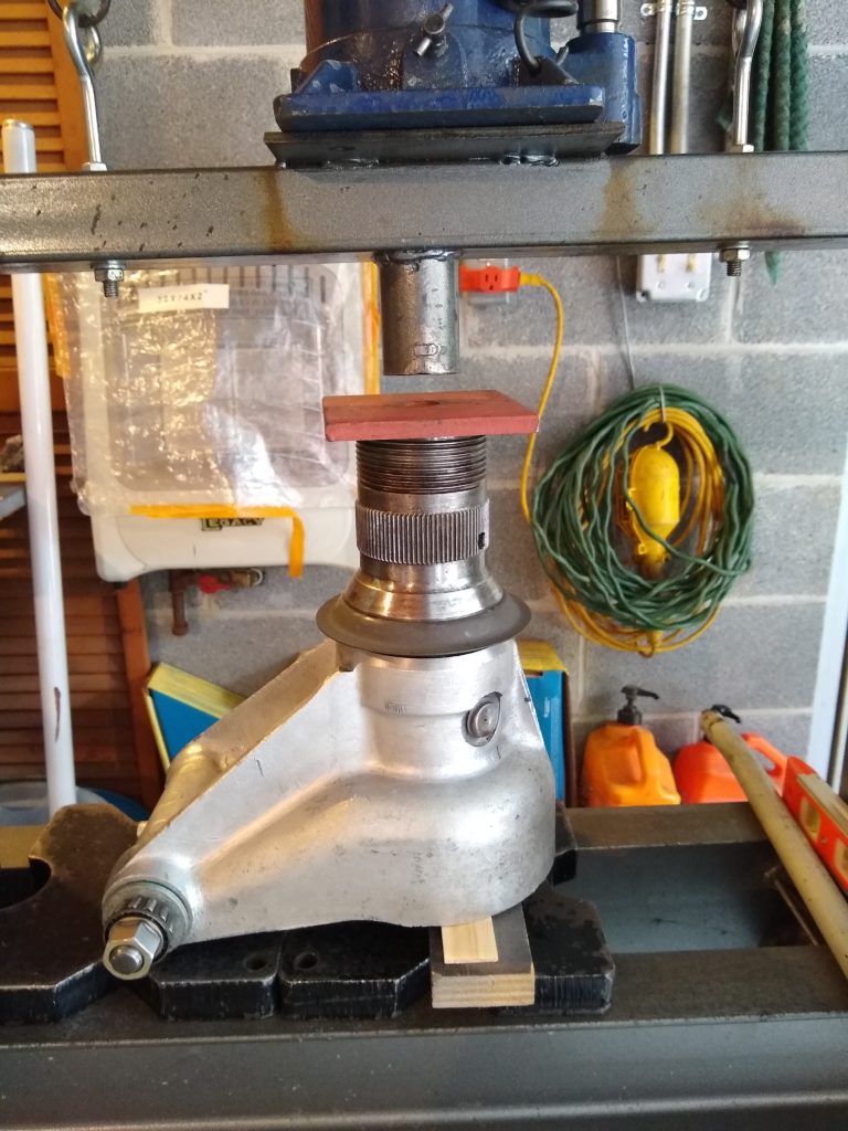
Take any thickness Spacer and place it on the end of the Hub. It does not matter what Spacer thickness you choose, just grab one to get started. In this picture we put a Spacer that is high in relation to the Bearing Face. Just a random Spacer. You can tell it is high by holding the gauge flat across the Spacer (that is sitting on the end of the Hub) and let it overhang the Bearing Face. Then tip it downwards towards the Bearing Face. It rocks! The Spacer is too thick. So we found another, thinner one. We measured the thickness of the first Spacer and found one thinner. It doesn’t matter how much thinner at first but you do develop a feel for what thickness relative to the previous Spacer you are looking for. This next picture shows our second choice. When placed on the end of the Hub and the gauge placed across the Spacer and the Bearing Face, there was an obvious gap between the bottom of the gauge and the top of the Spacer. The Spacer was held firmly across the Bearing Face. In the case of a Spacer being too thin, the Spacer can be moved back and forth – slid around if you will – under the gauge. That’s because it is not touching the gauge that you are firmly holding in contact with the Bearing Face. If the Spacer is too thick, you’ll be able to rock the Gauge over onto the Bearing Face. Both of these last two pictures are of a Spacer that is too thin. In the second one I’m holding the Maury Gauge firmly across the Bearing Face while sliding the Spacer around under it. Too thin! We need to find a Spacer thicker than this one but thinner than the previous one. Note I am not telling you what the Spacer thicknesses are. It does not matter; it only matters that you find one that is just right – the “baby bear” of Spacers from the children’s fairy tale!
The process is so simple it is unbelievable! It took about 10 minutes to find a Spacer of the correct thickness. Of course, Dick had a pile to choose from making it easy. Be careful in selecting the Spacers because we noted several whose thickness varied around the circumference. You don’t want that as it will create unwanted pressure points on the Hub’s end or the Inner Seal Seating Ring, or both, and that would not be desirable.
Another warning: I had new Spacers I brought to Dick’s garage, none of them measured what I ordered nor what was stamped on their edges. Two of the same stamped thickness measured differently. Be alert to these discrepancies, measure everything, don’t rely on the stated value.
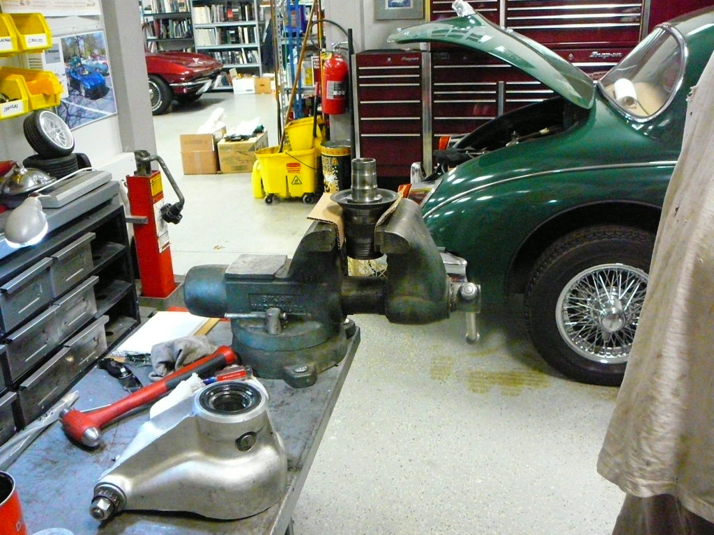
With the Spacer determined that was level with the Bearing Face, it was a simple matter to press in the Inner Seal and fit the Inner Seal Seating Ring into the Inner Seal. We could have left the Seating Ring on the Splined Shaft but the Seal was tight enough to hold the Ring in place and we slid the Splined Shaft into the Hub and nutted it up.
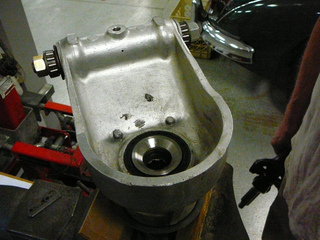
As a test of the efficacy of Dick’s method, he had me do the next Hub. I let him press the Outer Bearing in place as his floor press is different than mine but then I took over and pressed the Inner Bearing onto the Hub. I first found the point where the Bearing felt a bit too tight. Then Dick knocked the Hub Carrier upwards with his big rubber hammer. At that point I felt I could wobble the Hub Carrier relative to the Hub and I gently tapped the bearing down. Still a little noticeable wobble and a bit more tapping, and again until I zeroed in on a position of no wobble and not too tight. Not too loose, not too tight! Dick checked my work and approved it. This is a piece of cake! The finished product is below. It was an awesome exercise, experience and learning project for me. Altogether it took about 3 hours to complete two Hubs that only had their Bearing Cups installed. Well and the Fulcrum Shaft was installed, but that didn’t matter. Dick spent a great deal of time explaining to me what he was doing and why and then waiting while my thought processes caught up with his. That took a while! Frankly, I had to get back home and make a drawing to fully understand why this Maury Method works. I’ll share that with you next. But before we get into that detail, here is the finished Hubs and Axles. All in all, it may have taken Dick an hour to do this job if I weren’t there to bother him.
to Go
Details and Explanations
Now for some details and explanations about the Hub and Hub Carrier geometry and Jaguar’s special tool and to show that the Maury Method is in accord with Jaguar’s method from the Service Manual. They are not the same however. Jaguar created a method that does not rely on a mechanic’s “feel” or experience; it will result in a properly set up set of wheel bearings. The Maury Method requires an understanding of the process and requires some judgement by the mechanic. That said, the Maury Method is no more difficult than what mechanics do every day in changing tapered bearings on an axle like that found in a typical trailer or the wheel bearings on the front of a typical automobile.
We’ll start with a diagram that came from the Jaguar “E” Type Service Manual, Publication No. E/123/8 – E/123B/3 – E156/1. I modified this diagram and the following one from the same source to colorize it and focus their purpose to be more in line with this article.
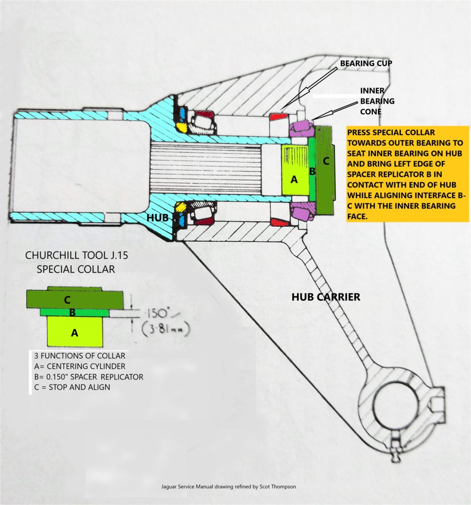
The above diagram shows the relationship between the Hub, the Hub Carrier, the Bearings, and the special tool Jaguar made available to aid in setting up the wheel bearings. This discussion may be basic for many of you who have worked on the E-type for years and/or who have professional level mechanical skills. But it will hopefully make clearer how the Rear Hub System works and how to set it up properly. With that in mind then, the E-type Tapered Wheel Bearings are mounted on the Hub in such a way that they not only support the radial load, but they oppose each other and hence can withstand the axial thrust load as well. As long as they are set up properly. This is nothing new and cars have been using tapered bearings for more than a century. The Cups these bearing ride in are firmly pressed into their positions within the Hub Carrier and the Hub Carrier is “fixed” to the car while allowing for suspension movement. The Hub spins, the Hub Carrier does not. In order for this system to function, the bearings must ride in their cups with just the right amount of force pushing them together. This force is called Pre-load. Pre-load keeps the bearing rollers constantly under load so they don’t rattle or shake and damage their cups or rollers and at the same time support the car as it moves, absorbs bumps and braking and high speeds. Earlier in this article I mentioned that Jaguar designed the E-type with a bearing specification based on some end-float, or allowed movement between the Inner and Outer Bearings, and that industry standards have improved over the years and the current practice is to pre-load these types of bearings. This article concurs with that practice and hence is disagreement between this article and Jaguar’s 60-year-old specification.
The process of setting either modern pre-load or the previous practice of end-float is exactly the same however. The difference lays in the specification. Jaguar’s end-float practice called for end-float of between 0.002” and 0.006”. Often referred to as the mean between those two values, or 0.004”. Current practice calls for 0.000” (as in zero) of end-float or less, say a negative end-float of 0.001” or 0.002”. That negative value means the bearings are actually squeezed together a bit – hence they are under pre-load.
In the diagram, the green (multiple-green colors) Special Collar Jaguar designed has several functions to it although it is a single piece of metal. Part A keeps the tool centered with respect to the Hub. Part B is going to sit on the inner end of the Hub as a Spacer Replicator. Part C provides a surface that sits on the Bearing Face and assures the Spacer Replicator’s (Part B) surface is in the same geometric plane as the Bearing Face. It should be obvious in the above diagram that the Special Collar will press the pink colored Inner Bearing Cone towards the Outer Bearing until such a point that the Part B touches the end of the Hub. When that happens, the Bearing Face will be exactly 0.150” away from the end of the Hub. (Because that is how thick Part B is.)
As it turns out, an actual Spacer that is 0.150” will also keep the Bearing Face 0.150” away, or proud of, the end of the Hub. Recognize that 0.150” is too much distance for the bearing’s setup as the Inner Bearing would not be firmly in its Cup. But, using the Special Collar, when in place, allows a measurement to be taken by pushing and pulling the Hub in to and out from the Hub Carrier. The Service Manual isn’t really clear as to how one accomplishes this while the Hub/Hub Carrier assembly is still in the Floor Press, but I assume one uses two screw drivers or levers to pry up the Hub Carrier while the Hub remains pressed between the ram and the bolster of the press. Lifting the Hub Carrier in itself is tricky as it is easy to tilt the Hub Carrier while lifting it in two different places; tilting the Hub Carrier will give a false reading. Assuming you make a perfect lift, let’s see how you use the information. As the Service Manual states in its example: assume the difference between the Hub pressed all the way in to the Hub Carrier and the Hub Carrier lifted all the way off of the Hub measures 0.025” (this is measured end-float). By using the mean desired end-float of 0.004” and subtracting that from the measured end-float of 0.025” you’ll find it to be 0.021”. Subtract this number from the Special Collar’s Part B thickness of 0.150” and the value will be the Spacer necessary for bearing setup according to the manual’s 0.004” End-float; in that case a Spacer = 0.129”. Therefore, a Spacer of 0.129” thickness is required to produce an end-float of 0.004”. Right? Yep! But, “we don’t want any end-float”, you say.” Indeed! Not by today’s practice. So, subtract that 0.004” mean end-float from the 0.129” and the result is 0.125” and that would be the Spacer thickness required to produce no end-float and no pre-load. Isn’t that confusing?!
I think so. And that is not all! In order to verify you have it right, you have to remove the Special Collar, Insert the Splined Shaft with its Inner Seal Seating Ring in place (and maybe the entire Half-Shafts/U-Joints/Flange assembly to boot!), and torque it down and measure the amount of end-float and hopefully find there isn’t any because that is what you wanted. And perhaps take it all apart again if it was mis-calculated. Isn’t there a better way?
Let’s look at the next diagram. The Green thing is the Spacer. It sits in exactly the same place as Part B of the Special Collar in the previous diagram. The object is to find a Spacer of exact thickness so that the right side of the green Spacer (the diagram’s right) is exactly flush with the Inner Bearing Face when the Inner Bearing has been pressed far enough onto the Hub to the point where the Hub Carrier doesn’t wobble and the Bearings aren’t too tight. This is the judgement part of the Maury Method. Still, as explained earlier in this article, it is quite easy to achieve proper bearing pre-load. Once you have that, finding the correct Spacer is the simple iterative process described earlier in this article.
You now know why the Maury Method works, how it is accomplished, and why it achieves the same result as using the Special Collar.
Fixing Wheel Bearings On The Road
As promised on Page 6, the following describes how one can apply this technique of setting proper bearing pre-load with the Hub still on the car.
Should you find yourself on the road with a wobbly rear wheel as a result of wheel bearings that are too loose, you can make a gauge out of a metal ruler or any piece of metal that is nice and straight on at least one edge. It does not need to have one side longer than the other, just make it 2-1/8” so it will fit inside the Inner Bearing Seal. With a gauge in hand, proceed as follows.
First remove the lower grease fitting so when the hub pivots around the Fulcrum Shaft once free of the axle, the grease fitting will not break off when it encounters the Wishbone. There isn’t sufficient room between the Wishbone and the Hub Carrier to accommodate the grease fitting. Undo the outer large nut inside the hub that is constrained by a cotter pin and has the thick washer under it. The hub must come away from the axle. More often than not, and if you’re lucky, the splined shaft and its connected half-shaft will slide out of the hub as the hub rotates down. With the hub pivoted down and its outer end facing the ground, the Inner Bearing and Spacer will be right in front of you. Or perhaps the Spacer stayed on the Splined Shaft and in that event simply retrieve it.
Assuming the Bearings were loose and causing the wheel to wobble, it will need a thinner Spacer to tighten things up. Thinner is easier to deal with than thicker as you might imagine. Support the Hub (the spinning part, not the aluminum Hub Carrier) and tap the Inner Bearing further onto the Hub until all free play is gone but no further. Not too loose, not too tight. Using the method describe in this article, find the proper shim so when you put the assembly back together it will have 0.000” end-float (also this will have zero pre-load). If a thinner Spacer is needed and you don’t have an available selection, the existing one can be sanded down. Measure the thickness carefully prior to sanding and note it. Then measure after sanding to make sure not too much metal is taken off, note that thickness and fit it to the hub and apply the gauge again. Be very careful to sand off an equal amount all around the Spacer so it remains flat. Repeat sanding and measuring and applying the gauge until you are satisfied. Some cars have brass Spacers and they are much easier to sand but steel ones just take longer.
The end